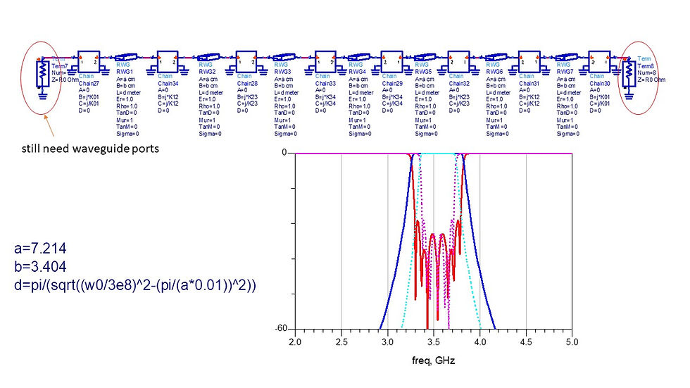
Design a bandpass waveguide filter
- YAOWEN HSU
- 2022年3月25日
- 讀畢需時 1 分鐘
已更新:2022年7月7日


%Chebyshev BPF waveguide prototype
close all;home;clc;clear all;
%input
N=7;
Am=0.01; %ripple level in dB
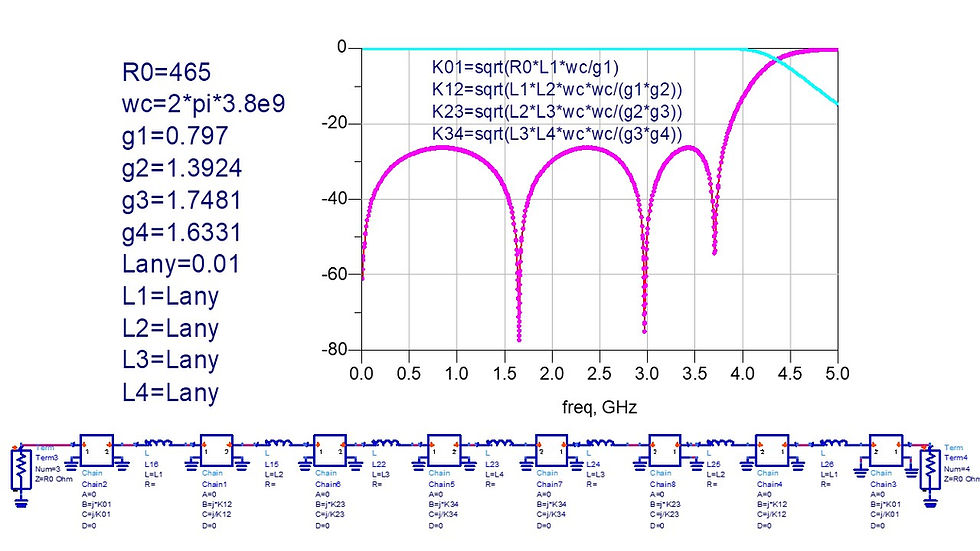
R0=465;
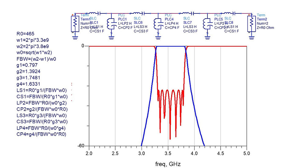
W1=2*pi*3.3e9;
W2=2*pi*3.8e9;
W0=sqrt(W1*W2);
FBW=(W2-W1)/W0;
%================================================
beta=log(coth(Am/17.37));
gamma=sinh(beta/(2*N));
for k=1:1:N
a(k,1)=sin((2*k-1)*pi/(2*N));
b(k,1)=gamma^2+(sin(k*pi/N))^2;
end
g(1,1)=2*a(1,1)/gamma;
for k=2:1:N;
g(k,1)=(4*a(k-1,1)*a(k,1))/(b(k-1,1)*g(k-1,1));
end
g(N+1,1)=1;
for k=1:1:N;
kt=mod(k,2);
if kt==1;
CL(k,1)=1e6*(g(k,1)/FBW)*(R0/W0);%series L unit uH
CL(k,2)=1e15*(FBW/g(k,1))/(W0*R0);%series C unit fF
else
CL(k,1)=1e9*(FBW/g(k,1))*R0/W0;%series L unit nH
CL(k,2)=1e12*(g(k,1)/FBW)/(W0*R0);%series C unit pF
end
end
CL
Scaling to BPF proto type

Apply impedance inverters to LPF prototype
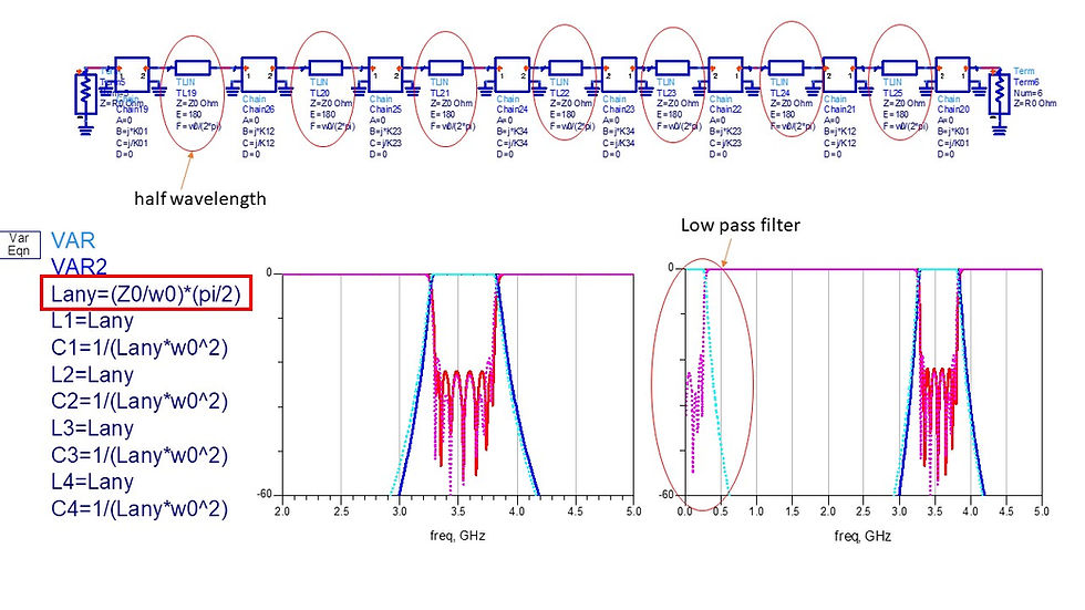
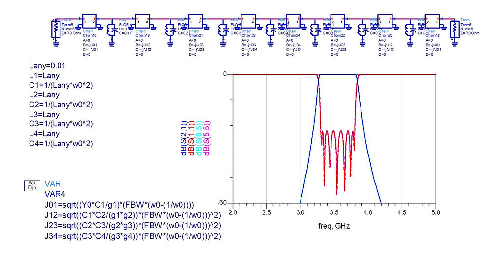
Mapping to BPF (equations) and use K inverter

L and C must maintain the relationship C=1/(L*w0^2)
Frequency mapping exists in K inverters, using the factor (FBW*(w0-(1/w0)))^2


In[91]:= w1=2*\[Pi]*3.3*10^9;
w2=2*\[Pi]*3.8*10^9;
w0=\[Sqrt](w1*w2);
FBW=(w2-w1)/w0;
R0=465;
Y0=1/R0;
g1=0.797;
L1=(R0/w0)*(\[Pi]/2);
pC1=(1/(R0*w0))*(\[Pi]/2);
K01=\[Sqrt]((R0*L1/g1)*(FBW*(w0-(1/w0))))
pJ01=1/\[Sqrt]((pC1/(R0*g1))*(FBW*(w0-(1/w0))))
Out[100]= 245.298
Out[101]= 881.478
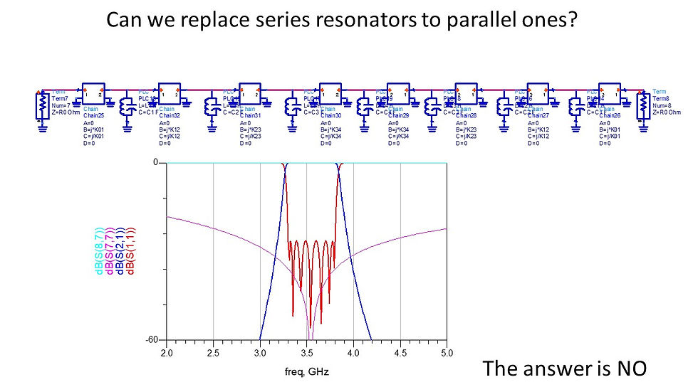
Different inverters but the same results!!


留言